
CNCDIY Club
Share your experience with CNCDIY's Machine
|
| | | Step loose & VFD controler overheat on BORCH 9060 |  |
| | | Author | Message |
|---|
ewidance
Posts : 10
Join date : 2011-04-19
Location : Montpellier / France
|  Subject: Step loose & VFD controler overheat on BORCH 9060 Subject: Step loose & VFD controler overheat on BORCH 9060  Tue Apr 19, 2011 12:36 am Tue Apr 19, 2011 12:36 am | |
| For information, i already own a CNC, and i'm electronic design engineer. That helps.... I've setup the machine, and it appears to loose steps at any speed, and do a lot of bad noise (vibrations). I suspect an electronic noise problem. I also tested the spindle, with a 10 Hz PWM signal as written on the manual. Spindle was running fine. I have got an other controller using also TB6560 (different design), but without spindle interface (see http://www.civade.com/post/2010/12/20/Rack-de-commande-CNC-%C3%A0-base-de-TB6560-%3A-vid%C3%A9os-de-pr%C3%A9sentation ). I adapted cabling of my controller so i could replace yours. Motors where running nicely up to 1600 mm / min. The noise was really nice and there where no more vibrations. So the problem is on your controller. On yours, opto-coupling is done directly on driver board. The signal path between break-board and controllers is not protected by shielded cables. I tested one of the boards using a signal generator (400 Hz pulsed, 10 % ratio) and a spare 3A motor to isolate break-board on 1 axis. Signal was injected directly on the board, without going thru the break-board. Motors were sill missing steps. Next, i unsoldered the optocouplers and injected directly the signal on the step pin of TB6560. Controller was still missing steps. I suspect a design / routing problems on the printed circuit for grounds. I checked signals using oscilloscope. STEP / DIR / ENABLE were relatively clean. I also check the logic alround the ultivibrator wich is lowering automatically the current in ther's no step pulse during the two last seconds. That work. To help me in that investigation, and more generally about the machine, many documentations are missing from your website (BORCH 9060 with VFD spindle and CB-B4-001 controller): * Manual of the spindle itself. * Manual of VFD control board, with procedure for adjusting it, and explanations of connector pinout, pushbuttons role and display / LEDs role. * Data-sheet of stepping motors. It would be easier to adjust with load curves. * Manual of stepping controllers, ideally with schematics, and printed circuit. * Manual of parallel port break-board, and specially pinouts of unused connectors (for later addition of limit switches) Nota: If you've got only chinese documents for certain manuals, don't hesitate to give it to me. I'll use translation software.... I'll give you feed back about my investigations on how to fix the noise problems (if possible... because if it's a printed circuit routing problem, i will not be able to fix..). I'm interested on helping impoving the machine. Sincerely, JPC
Last edited by ewidance on Tue Jun 07, 2011 10:21 am; edited 4 times in total | |
| | | | ewidance
Posts : 10
Join date : 2011-04-19
Location : Montpellier / France
| | Subject: Re: Step loose & VFD controler overheat on BORCH 9060 Wed Apr 20, 2011 11:50 pm | |
| There are some config problems on Borch 9060 with EMC2 2.4.6 . First, there's a bug in EMC2, avoiding the popup of PWM control panel at the end of stepconf wizard. EMC2 don't check for PWM on pin 17, due to a bug in the code. This bug is already fixed in Git repository and will be probably fixed in next version. See here in Git repository : http://git.linuxcnc.org/gitweb?p=emc2.git;a=commit;h=fc88672c230666ec0d5d512f60fd131425bd85e4To fix it, edit stepconf.py, and replace - Code:
-
return PWM in (d.pin1, d.pin2, d.pin3, d.pin4, d.pin5, d.pin6, d.pin7,
d.pin8, d.pin9, d.pin14, d.pin16) or \
with - Code:
-
return PWM in (d.pin1, d.pin2, d.pin3, d.pin4, d.pin5, d.pin6, d.pin7,
d.pin8, d.pin9, d.pin14, d.pin16, d.pin17) or \ Se details in http://git.linuxcnc.org/gitweb?p=emc2.git;a=commitdiff;h=fc88672c230666ec0d5d512f60fd131425bd85e4;hp=dabdc1c152f42b7af4771cc9bf9867c368896c6dAfter that fix, the pwm windows will properly display at the end of stepconf wizard. Second, there's a mismatch in PWM configuration for CB-B4-001 controller in the manual. The adjustment of spindle is inverted. Correct values should be : PWM RAte: 10 Hz Speed 1: 0 PWM1 : 1 (to invert ratio)Speed 2 : 25100 (to avoid a bug)PWM2 : 0 (to invert ratio)Third, when loading Gcode on EMC2 and starting it, programs starts immediatly to mill while spindle has not reatch is speed!!!! That's very dangerous.... I've been on IRC with EMC team last week and they help me to solve the problem. It needs to add code to custom.hal in the conf of the machine. That code insert an ramp in spidle circuit, allowing to wait for a time enough to let spidle gets it's speed. That ramp is setup with a parameter secifying number of RPM per second the spindle can accelerate. CUSTOM.HAL : - Code:
-
# soft start On spindle
# load real time a limit2 and a near with names so it is easier to follow
loadrt limit2 names=spindle-ramp
loadrt near names=spindle-at-speed
# add the functions to a thread
addf spindle-ramp servo-thread
addf spindle-at-speed servo-thread
# set the parameter for max velocity (rpms's per second)
setp spindle-ramp.maxv 600
# hijack the spindle speed out and send it to spindle ramp in
net spindle-cmd <= motion.spindle-speed-out => spindle-ramp.in
# unlink pin already wrapped from stepconf wizard...
unlinkp pwmgen.0.value
# the output of spindle ramp is sent to the pwmgen.0.value
net spindle-ramped <= spindle-ramp.out => pwmgen.0.value
# to know when to start the motion we send the near component
# (named spindle-at-speed) to the spindle commanded speed from
# the signal spindle-cmd and the actual spindle speed
# provided your spindle can accelerate at the maxv setting.
net spindle-cmd => spindle-at-speed.in1
net spindle-ramped => spindle-at-speed.in2
# the output from spindle-at-speed is sent to motion.spindle-at-speed
# and when this is true motion will start
net spindle-ready <= spindle-at-speed.out => motion.spindle-at-speed
the "setp spindle-ramp.maxv 600" fix the step of ramp, here 600 rpm per second. This seems to be the max value. You can setup to 400 or 500 to be sure spindle has reached the assigned speed. | |
| | | | ewidance
Posts : 10
Join date : 2011-04-19
Location : Montpellier / France
| | Subject: Re: Step loose & VFD controler overheat on BORCH 9060 Sun May 15, 2011 1:10 pm | |
| Since i count not make the stepper work proprely, i've changed it. I've used an other YB6560 based controller and replaced th one shipped. After some hours of work, cabling, testing, etc.. that works.
This cost me 60 USD + the time to install.
But after trying to make the first carvings, I found another bug on Borch 9060:
When running@ 12000 RPM, VFD controller stop and goes on 'error' after half an hour. It's possible to restart the motor before shutting of and on the controller to reset the error.
After investigations, it appears the VFD controller have got a big dissipator under it. The board is sticked yo the bottom of the box. Power supply fan (a small 30mm) is supposer to give fresh air to VFD dissipator. Its clearly not enough.
The VFD controller have got a function to mesure temp. I've used it and without fan it goes up to 80 Celcius degrees... and stops. Clearly too much.
I had to modify the controller to lift the VFD board of 50mm from the box bottom. In that space I put a big fan (120mm), and opened a hole in the bottom of the controller.
After the modification, temp don't go over 55 celcius.
I'm very disapointed. Electronic on that machine is a pity. Very bad design... I already spend many many hours to improve it... | |
| | | | ab
Posts : 14
Join date : 2011-01-26
| | Subject: Re: Step loose & VFD controler overheat on BORCH 9060 Tue May 17, 2011 12:41 am | |
| Good to know you're making progress. I haven't had any issues with the VFD overheating (even after running straight for 7 hours) but I certainly had issues with the stepper drivers and stepper motors getting crazy hot. I ended up adding massive heat sinks to the motors and a bunch of fans to each driver and some additional case fans. Everything is now cool to touch, even after 7 hours!  I'll have to do some temperature testing on the VFD to ensure it is running ok too. Here's a pic of my 'tie fighter' steppers 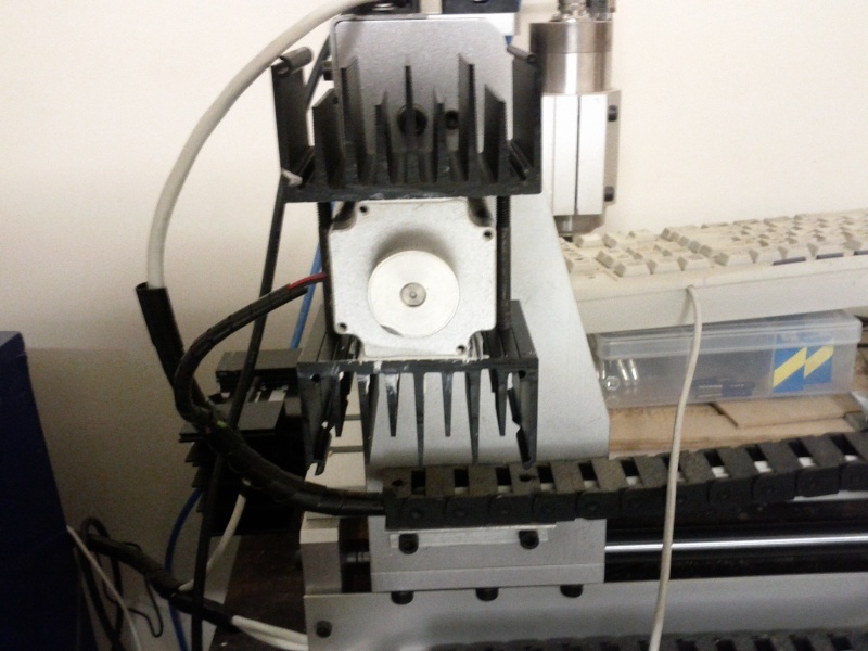 Only downside is that they have added a resonance to the motor steps. Each time the motor moves, the fins of the heat sink vibrate ever so slightly and 'sing' to me Andrew | |
| | | | cncdiy
Admin
Posts : 45
Join date : 2010-01-13
| | Subject: Re: Step loose & VFD controler overheat on BORCH 9060 Wed May 18, 2011 11:32 am | |
| Thank you ewidance for you information!
Can you provide more information about your founding and solutions and recommendations in graphic details?
We would like to refund a part of money to you for your improvement.
I hope to receiving from you soon!
CNCDIY | |
| | | | ewidance
Posts : 10
Join date : 2011-04-19
Location : Montpellier / France
| | Subject: Re: Step loose & VFD controler overheat on BORCH 9060 Fri Jun 03, 2011 3:18 am | |
| To ab : The overheating only appears when running alround 12000 rpm. It's a gauss curve centered @12000. So if you run @6000 or @18000 rpm, it's (almost) quiet and does not overheat. To test, you should absolutely go @12000 rpm and leave it run for 15 to 30 minutes. Then the spindle will stop.... (error condition on the controller). I did not have any overheating problems on steppers, but I changed the stepper controller and then modified it. I wrote (in french) a paper in my blog, about the TB6560 modification. In french : http://www.civade.com/post/2011/05/27/Controleur-pas-a-pas-Toshiba-TB6560-datasheet-probleme-horlogue-haute-vitesse-perte-pasIn english (google translate): http://translate.google.com/translate?hl=en&sl=auto&tl=en&u=http%3A%2F%2Fwww.civade.com%2Fpost%2F2011%2F05%2F27%2FControleur-pas-a-pas-Toshiba-TB6560-datasheet-probleme-horlogue-haute-vitesse-perte-pas This modification also apply to the TB6560 drivers shipped with the machine. In short, TB6560 has an internal clock for generating microsteps. This clock is setup by a onboard capacitor, which is not the right value (frequency too low). The installed value (330pF) does not allow hi speeds without 'forcing' on decay. Replacing this cap by a 100pF on all axis allows to go 4xtimes faster. This capacitor is called "C2" on Borch 9060 controllers. I changed it on each of them and test, it was far away better. Would you please post your switch settings, and a picture of your controller, so i could have a look on your stepper overheating problem... This sould not happens, since current seems to be factory limited to a max of 2.72 amps on borch controllers... and motors are 3 amp. To cncdiy : Thanks for you offer. I have not finished improvements. I'll post you the modifications as soon it will be complete. | |
| | | | ab
Posts : 14
Join date : 2011-01-26
| | Subject: Re: Step loose & VFD controler overheat on BORCH 9060 Sun Jun 05, 2011 6:54 pm | |
| That's weird. I run mine at 12000 for 5-6 hours straight and never a single problem. I've run it at a range of speeds from say 1000 up to 24000 for many hours each and it's been fine.
What inverter to you have? Mine is the Fuling DZB200.
Regarding the stepper drivers. Mine came with separate drivers and signal isolation boards (Not the all in one board like yours). They are all branded 'yoocnc' but I've never been able to find too much information on them. They were overheating like crazy when on for an extended time but after I put fans on each one and beefed up the case fan they run very cool | |
| | | | ewidance
Posts : 10
Join date : 2011-04-19
Location : Montpellier / France
| | Subject: Re: Step loose & VFD controler overheat on BORCH 9060 Mon Jun 06, 2011 1:10 am | |
| I understand... Your VFD controller is external.... On 9060, the VFD controller is integrated into the command rack with stepper motor command. It's a control board, not a complete external vfd contrôler. Into the rack, as shipped, there's no dedicated fan to cool the vfd dissipator. It 'shares' the 'fresh' air outgoing from the 30 mm / 24 volts power supply fan. That's clearly not enough to cool the VFD controller... But board is ok and works file. I's only a cooling problem. After integrating fans, I've made an other modification. Most of the time, there's no need of impressive cooling. Little one is enough. It's only when running @12000 rpm (and alround) it's mandatory. My goal was to drive fan progressively between 2 temperatures : * 25 -> 35 celcius for spindle watercooling * 25 -> 45 celcius for VFD controller dissipator. Since there where no products on the market able to to that for nice pricing, I've designed a 2 channel temperature controlled fan controller, based on Arduino ( http://translate.google.com/translate?js=n&prev=_t&hl=fr&ie=UTF-8&layout=2&eotf=1&sl=fr&tl=en&u=http%3A%2F%2Fwww.civade.com%2Fpost%2F2011%2F05%2F25%2FSnootlab-Essai-de-l-Arduino-i2C-Power-proto-shield-ventilateurs-pwm-ds1820-fanduino , see at the end of the post). Cost is 15 USD (freeduino) + 2 sensors (3 USD each) + 2 Mosfets (1 USD each) and some resistors. One channel is for the fan i've integrated at the bottom of the command rack for vfd, and the other channel is for external 2 X 120 mm fans, located on watercooling dissipator (http://www.frozencpu.com/ex-rad-46.html ) i've bought for 20 USD on Ebay. Temperature sensors (Dallas DS1820) are located : * On the VFD controller dissipator itself for internal channel (glued with polyester resyn) * On the water input fitting (maintained by heat schrink tubing). I'm very happy with that hack. Now the machine is quiet. I ran @6000 rpm for may hours during the weekend, and fans where running slowly until I run for at least 30 minutes @ 12000rpm. Then fans goes progressively on... and off 10 minutes after switching off the spindle. Ewidance http://www.civade.com | |
| | | | aarggh
Posts : 2
Join date : 2011-06-07
| | Subject: Should the TB6560AHQ be Connected to common Earth Tue Jun 07, 2011 7:08 am | |
| Hi ewidance and all,
I have one of these 3 axis yoocnc driver units along with a water cooled 0.8KW spindle, and have seen many posts that that power supply, cnc, and spindle frame need to be connected to common Earth, but if the PSU is connected to Earth then the ALU heatsinks attached to the TB6560's will also be at Earth, is this dangerous for the chips? Should the IC tabs be at logic 0/digital ground, but not Earth?
I can't seem to find this info in the datasheets or anywhere conclusively?
cheers,
Ian | |
| | | | ewidance
Posts : 10
Join date : 2011-04-19
Location : Montpellier / France
| | Subject: Re: Step loose & VFD controler overheat on BORCH 9060 Tue Jun 07, 2011 7:25 am | |
| There's no danger to earth chassis, even for the drivers.
However, there's an isolation (opto coupling) between power stage, and control stage.
This opto isolation should take care of ground separation. There"s a bg chance the 24V groud is connected to chassis. By earthing chassis, you going to connect ground with earth.
If you ground spindle, motors, cnc chassis and so on, you should first verify (with an ohmmeter) the signal ground of the parallel port is totally insulated from power ground. | |
| | | | aarggh
Posts : 2
Join date : 2011-06-07
| | Subject: Re: Step loose & VFD controler overheat on BORCH 9060 Tue Jun 07, 2011 8:20 am | |
| Hi ewidance,
Thanks for responding, this is driving me up the wall1. That's a good point about the parallel port shell being connected to mains earth, technically it should be okay as long as the pc is also connected to the same mains feed as the machine, and controller unit.
As in the pc it will be touching the earthed computer case, and in the drive control unit even though the earth cable has been cut off (for some reason I don't understand) the output of the mains power input filter, the parallel port shell is screwed to the same metal panel the input filter is, so that's also at mains earth. I vaguely recall the 34xx? series form memory had to have the heatsink insulated from mains earth, or it blew the IC's, I just wonderred if the 6560 should also be insulated from the chassis?
Okay, just checked with the meter:
-5V is common with mains earth connection tap of the PSU and the bottom ALU panel and the heatsinks of the drivers.
Mains earth pin on mains input filter is common with back ALU panel and also the parallel port shell.
So to my mind the cnc machine and spindle should be earthed via a screw on the back panel where the mains input filer is, this will give a common earth for the PC, controller power input with parallel port, and the CNC frame/spindle, which should take care of any feedback from the mains/spindle to the steppers.
But...this is where i'm not sure, to my mind the PSU really SHOULD be at mains earth, but to protect them, if the driver heatsinks are insulated from the base panel, and therefore mains earth, the -5V rail is still common to mains earth, so connecting mains earth to the PSU will still blow the IC's? Does the PSU need to stay isolated from mains earth as the -5V supply is common to it?
cheers,
Ian
| |
| | | | ewidance
Posts : 10
Join date : 2011-04-19
Location : Montpellier / France
| | Subject: Re: Step loose & VFD controler overheat on BORCH 9060 Tue Jun 07, 2011 10:19 am | |
| | |
| | | | Sponsored content
| | Subject: Re: Step loose & VFD controler overheat on BORCH 9060 | |
| |
| | | | | | Step loose & VFD controler overheat on BORCH 9060 | |
|
Similar topics | |
|
| | Permissions in this forum: | You cannot reply to topics in this forum
| |
| |
| |
|